Sep. 28, 2026
Electromagnetic flowmeters are widely used in water treatment and other industries. They feature simple structure, reliable measuring performance and low pressure loss. Many beginners have questions about its measuring principle, installation requirements and fault handling. This article covers principle, grounding, installation, troubleshooting and selection for your reference.
💡 Important Note: The content below is for instrument knowledge reference only and does not constitute performance guarantees. Field conditions vary, and decisions should be made according to actual working conditions.
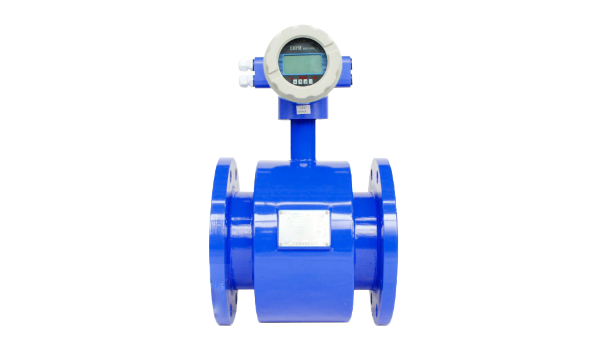
The core working principle: Induced electromotive force is generated when conductive fluid cuts magnetic field lines.
Magnets are mounted outside the measuring tube of the flowmeter, and a pair of electrodes are installed on the inner wall of the tube. When conductive liquid flows through the magnetic field area, the fluid acts as a conductor cutting magnetic lines. A weak voltage signal will be generated between the two electrodes. The faster the flow velocity, the higher the voltage value. The converter amplifies and converts this voltage signal, then outputs the flow reading.
Two basic prerequisites for using electromagnetic flowmeters:
Oil products, gas and steam are poor conductors, so they are not suitable to be measured by electromagnetic flowmeters.
Grounding is a critical factor for electromagnetic flowmeters. The instrument picks up microvolt-level weak voltage signals, which can easily be submerged by external interference. Many abnormal measurement issues are related to poor grounding. Common interference sources include large motor startup, frequency converter noise and stray current in pipelines. Unqualified grounding will cause unstable and fluctuating flow readings.
📌 Grounding Requirements
Field case reference: A flowmeter in a water treatment workshop showed fluctuating readings. After long-time inspection, the root cause was a loose grounding screw. The instrument returned to stable operation after tightening the screw.
Installation quality directly affects measurement stability. Please follow these installation recommendations:
Most blank screen issues are power-related. Check in sequence:
A small number of blank screen faults are caused by LCD damage. Traditional segment code screens are vulnerable to moisture and sunlight exposure. Only the screen needs replacement instead of the whole flowmeter.
| Fault | Possible Causes | Brief Explanation |
|---|---|---|
| Low flow reading | Electrode scaling | Sediment deposits on electrodes weaken signals. Clean electrodes and check lining condition. |
| Low flow reading | Partially filled pipe | Gas accumulates due to improper installation position. |
| Low flow reading | Poor grounding | Disconnected grounding circuit causes signal attenuation. |
| High flow reading | Harmonic interference from frequency converter | Nearby frequency converters introduce superimposed interference signals. |
| High flow reading | Bubbles in medium | Bubbles passing electrodes generate abnormal spike signals. |
| Unstable / high reading | Empty pipe condition | Electrodes exposed to air lead to chaotic signal output. |
📌 Key Reminder: For abnormal flow values, prioritize checking pipe fullness, grounding status and electrode scaling. These are the most frequent problems on site.
Beginners can focus on four core parameters: nominal diameter, lining material, electrode material and protection class. The table below shows selection suggestions for different working conditions.
| Selection Item | Recommended Option | Applicable Working Condition |
|---|---|---|
| Nominal Diameter | Match the pipe diameter; avoid random diameter reduction or expansion | Most standard pipelines |
| Lining Material | Rubber | Neutral medium such as tap water |
| Lining Material | PTFE | Acid and alkali corrosive medium |
| Lining Material | Polyurethane | Medium with solid particles, wear-resistant service |
| Electrode Material | 316L | Ordinary clean water |
| Electrode Material | Hastelloy | Sewage and corrosive fluid |
| Electrode Material | Tungsten Carbide | Medium with abrasive particles |
| Protection Class | IP65 | Indoor installation |
| Protection Class | IP68 | Outdoor installation or underground well with humid environment |
Electromagnetic flowmeters are widely adopted in water treatment, with simple structure, stable measurement and low pressure loss. Three core points help avoid most field problems:
✅ Ensure the medium is conductive
✅ Keep the measuring tube fully filled
✅ Complete reliable grounding
When basic application requirements are met, and installation standards are followed, with regular inspection of electrodes and grounding connections, the flowmeter can maintain stable operation.
Professional OEM & ODM Manufacturer
Tailored products to meet your complex working conditions.

Shaanxi NuoYing Automation Instruments Co., Ltd.
Navigation
Navigation
Contact Us
+86 182 1004 9286
+86 182 1004 9286
+86 182 1004 9286
Block V5, Ronghao Industrial Town, Gaoling District, Xi'an, Shaanxi, China.